Key takeaways
Site drainage in one minute
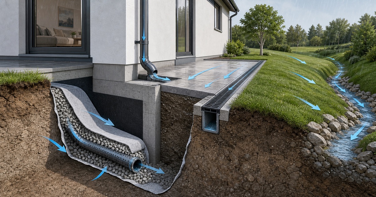
Site drainage is a coordinated system that collects rainfall and shallow groundwater, keeps it away from the building, and discharges it through a safe, maintainable outlet. A complete design addresses three separate jobs: surface grading moves runoff away from walls, channels or pipes convey concentrated flow, and subsoil drains relieve water in the ground. Installing a French drain without confirming levels, soil permeability, an outlet and an overflow route is not a drainage design.
- Start with levels. Water follows finished ground and pipe invert levels, not arrows on a concept plan.
- Separate water sources. Roof runoff, paved runoff and groundwater may need different collection methods.
- Design the outlet first. Every channel and pipe needs a legal discharge point plus a visible overflow route.
- Keep it serviceable. Inlets, silt traps, inspection chambers and outlets must remain accessible after landscaping.
What is site drainage in construction?
In construction, site drainage means the permanent and temporary measures used to control water across a property. It covers roof water after it reaches ground level, runoff from paving and landscaped slopes, seepage through soil, and water that could collect beside foundations or retaining walls. The objective is not simply to hide water in a pipe. The objective is to collect it without damaging the building, convey it without erosion or blockage, and release or store it at a suitable location.
Surface drainage and subsurface drainage solve different problems. Surface measures include falls, swales, slot or trench drains, catch basins and open channels. Subsurface measures include perforated collector pipes, free-draining aggregate, geotextile filters and inspection points. Roof gutters and downpipes form another input to the same site-wide water route. The final arrangement depends on rainfall, catchment area, soil infiltration, groundwater, topography, finished floor levels, neighboring land and local discharge rules.
A drainage plan should show where water starts, the level and route it follows, where it can be inspected, where it ends, and what happens when the normal route is temporarily overwhelmed or blocked.
System comparison
Types of site drainage and when they are used
No single drain type is best for every site. Good systems combine components according to the water source and the available outlet. The table below is a selection guide, not a substitute for hydraulic, geotechnical or local authority design.
| Drainage measure | Best used for | Main design check | Common failure |
|---|---|---|---|
| Grading and surface falls | Moving sheet flow away from walls, terraces and low points | Finished levels continue to a safe collection point without reverse falls | Landscape or paving changes create a trapped low area beside the building |
| Trench or slot drain | Collecting runoff across driveways, gates, thresholds and paved edges | Grate level, channel fall, outlet capacity and cleaning access | A narrow outlet pipe or silted channel becomes the bottleneck |
| Catch basin and solid pipe | Collecting concentrated surface or roof flow and conveying it downhill | Sump depth, pipe invert, junction access and downstream discharge | Debris enters the pipe because no silt trap or removable basket is provided |
| French or subsoil drain | Intercepting shallow groundwater and relieving wet soil beside structures | Perforated pipe level, clean aggregate, filter compatibility and a free outlet | The pipe has nowhere to discharge or the filter clogs with fine soil |
| Swale or bioretention route | Slowing, conveying and sometimes infiltrating runoff in landscaped areas | Longitudinal fall, erosion control, soil suitability and an overflow path | Standing water persists because infiltration was assumed rather than tested |
| Permeable paving | Reducing runoff from suitable patios, paths and parking areas | Subgrade permeability, storage layer, sediment control and underdrain need | Surface and base clog because construction sediment was not controlled |
The US Environmental Protection Agency describes swales as vegetated channels that transport water while slowing flow and supporting infiltration. It also notes that permeable pavement can store or infiltrate rainfall through underlying gravel, with an underdrain used where direct infiltration is unsuitable. These measures still need a site-specific overflow and maintenance plan.
Design workflow
How site drainage should be designed
- Map every water source.Mark roof catchments, downpipes, paved areas, uphill land, retaining walls, irrigation, springs and groundwater observations. Temporary construction runoff belongs on this map too.
- Survey controlling levels.Record finished floor, external threshold, paving, ground, wall footing, road drain and proposed outlet levels. Pipe gradients cannot be confirmed without invert levels at both ends.
- Define catchments and flow paths.Split the site into areas draining to each inlet or swale. Keep clean roof water separate from sediment-laden construction runoff where practical.
- Select and size components.Use local rainfall criteria and the contributing area to size channels, inlets, pipes, storage and overflows. FHWA's 2024 HEC-22 manual is a detailed reference for hydrologic and hydraulic drainage calculations, although local standards govern the project.
- Verify the discharge strategy.Confirm whether water may enter a public system, an approved outfall, storage, reuse or infiltration feature. Check downstream erosion, neighboring properties and the effect of high groundwater.
- Detail inspection and failure routes.Provide removable grates, sumps, cleanouts and chambers. Show where water will travel if an inlet blocks or a storm exceeds the normal design event.
Levels to coordinate before construction
Numeric slopes are jurisdiction-specific. For example, Ontario's stormwater planning manual discusses maintaining at least a 2% grade within roughly 2 to 4 metres of a building, while explicitly directing designers to check local municipal standards. Treat that as an example of a published criterion, not a universal rule for every project.
Worked example
A sloping house site in a high-rainfall climate
Consider a hypothetical house with an uphill boundary, a paved terrace on one side and a garden falling toward a lower road. The first design move is not to place a French drain around the entire house. The team surveys the road connection, finished floor, terrace and garden levels, then separates three water sources: clean roof runoff, fast surface flow from the uphill side, and damp soil beside the uphill retaining condition.
A shallow swale intercepts uphill surface water before it reaches the building. The terrace falls to a removable trench drain with a silt sump. Roof downpipes connect to sealed pipes rather than discharging beside the foundation. A localized subsoil drain relieves the wet uphill zone and terminates at an inspection chamber. All routes continue to the confirmed lower outlet, while the garden surface forms a visible overflow path that stays below the internal floor level.
This arrangement is more robust than one hidden pipe because each component has one clear job and can be inspected. The example still requires rainfall sizing, soil assessment, structural coordination and approval of the discharge point. It demonstrates the decision sequence: source, level, collection, conveyance, outlet, overflow and maintenance.
Budget control
What changes site drainage cost?
Drainage cost is driven less by the name of a product than by excavation, levels, water volume, soil, access and the distance to a usable outlet. Early coordination can keep drainage within normal external works. Late discovery can trigger demolition of paving, deeper trenches, pumping, retaining-wall changes or off-site approvals.
| Cost driver | Why it matters | Early evidence to obtain |
|---|---|---|
| Flat site or high outlet | Gravity drainage may require deeper excavation, storage or pumping | Topographic survey with outlet invert level |
| Clay, rock or high groundwater | Excavation, dewatering and infiltration assumptions change | Geotechnical observations and infiltration testing where relevant |
| Large roof and paved catchments | Peak flow increases inlet, pipe, storage and overflow requirements | Measured catchment plan and local rainfall criterion |
| Restricted site access | Excavation, spoil removal and aggregate delivery become less productive | Logistics plan and realistic plant access |
| Late landscape changes | New walls, planters and paving can block the designed flow path | Coordinated finished-level drawing before procurement |
| Unapproved discharge | Redesign may require detention, reuse, infiltration or another connection | Written confirmation of the permitted outlet strategy |
Construction check
Site drainage checklist before handover
- Finished ground and paving visibly fall away from vulnerable walls and thresholds.
- Every downpipe has a confirmed discharge route and does not empty beside the foundation.
- Channel grates are removable and set below adjacent paving without creating a trip edge.
- Catch basins include accessible sediment collection space where debris is expected.
- Pipe inverts and gradients match the approved drawings and have been surveyed where concealed.
- Subsoil drain aggregate and geotextile match the soil and specification.
- Inspection chambers and cleanouts remain accessible after planting and hardscape completion.
- Outlets are stable, legal and protected against erosion, backflow and animal entry where relevant.
- The overflow route stays outside the building and does not transfer water to neighboring land.
- A controlled water test confirms inlets, channels and outlets before final acceptance.
Ponding beside walls, silt marks across paving, overflowing grates, damp retaining walls, soft landscape edges, erosion at outlets and persistent water in inspection chambers all justify investigation before finishes conceal the cause.
Primary references
Sources and scope
This guide explains coordination and selection principles. Project design must follow local rainfall data, building and stormwater rules, geotechnical advice and the approved discharge arrangement.
- FHWA, Urban Drainage Design Manual, HEC-22, Fourth Edition (2024) - hydrologic and hydraulic design of collection, conveyance, discharge and detention systems.
- US EPA, Types of Green Infrastructure - current descriptions of swales, permeable pavement, bioretention and underdrains.
- US EPA, Stormwater Management Practices at EPA Facilities - examples of grading, swales, permeable surfaces and other low-impact measures.
- Ontario Stormwater Management Planning and Design Manual - an example of published lot-grading and foundation-separation criteria that must be checked against local standards.